Posts

gear backlash woes

Image
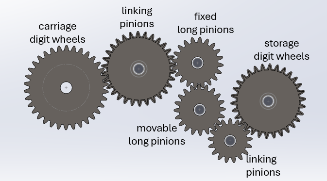
 Changing the long pinion meshing to be to the inner gear solved the problem of bogus multiplication by 1.35. But now there is another problem:  random subtraction of 1. The root cause is excessive gear backlash. When configured for addition there are four gears between the digit wheel that is "giving off" a source digit and the digit wheel in the adder ("anticipating carriage") that receives it.  If I hold the destination carriage wheel I can wiggle the source wheel almost a complete tooth -- which is a full digit -- without it trying to move the destination.  In doing a transfer I can get it to work correctly by "preloading" the gear train. But if I don't do that, then the first digit being given off might be absorbed by the slop in the gear train. This is clearly a major problem. There are three contributors to the backlash: The center-to-center spacing of the shafts is slightly larger than the gears were designed for, which had to be done to make m...

fixing a gear ratio problem

Image
 After various mechanical tweaks to allow too-tight gears to turn, the prototype is starting to come to life. But even just moving a number from one digit stack to another disclosed a bug: in the process it multiplies by 1.35! Sort of. Here's the deal... Changing a number wheel by one digit up or down means rotating it about the axis by 360/(3*10) = 12 degrees, because there are three repetitions of the digits 0 through 9 around the circumference. Since there are 30 teeth on a digit wheel, each full tooth movement represents a change of one digit. When a chain of gears is linked together, a movement by exactly one tooth is propagated unchanged through all the gears -- regardless of the diameter and number of teeth of the intermediate gears -- as long as all the gears have the same tooth pitch. That is a parameter called the Diametral Pitch (DP), which is the number of teeth per inch of diameter of the contact circle of the gears. Following Babbage's Plans from 13 through 28, I ...

"programming" the prototype

Image
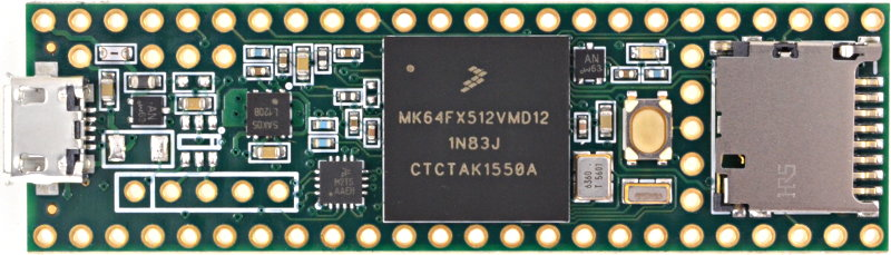
  Now that the prototype shows signs of coming to life, it is time to consider how to animate it. The axles are rotated and lifted from the "21st century" section on the bottom that is filled with stepper motors controlled with a PJRC "Teensy 3.5" microcomputer. Here are comments from the source file of a motion script interpreter I have written for it:    The following axles are implemented in this first prototype:           C    carry sectors for adding 1       F    the anticipating carriage digit wheels       FC   the connector pinion for above to FP       FP   the fixed long pinions       FPC  the connector pinion for above to either A1 or A2       MP   the movable long pinions       MPC  the connector pinion for above to either A1 or A2       A1   the upper number i...

ditching the lifter springs

Image
The initial version of the prototype had all the axles fixed. Vertical motion was effected by moving sleeves surrounding the axles that the components to be lifted (digit fingers, pinions, carry levers, etc.) would be trapped between. When the lifter was lowered, a spring on the top would push the components back down. There were two problems with this approach: The sleeves were long and introduced too much friction sliding against the axles. The spring force was often inadequate to move the components down. Besides, Tim Robinson says that Babbage never wanted to depend on either springs or gravity for positive motion. Consequently I redesigned the lifters so that the components are fixed permanently to the axle, and the axle is driven positively to move both up and down. The components are still spaced and trapped by concentric sleeves, but they are fixed in position and don't slide on the axle. Here's what the drive mechanism on the bottom looks like for a rotating shaft that...

a better locking mechanism

Image
Tim Robinson came by to see my prototype and had a number of excellent suggestions. One of the problem areas we discussed was my locking mechanism, which is based on a rotating wedge. It doesn't work well in moving the digit wheel away from the wedge pivot point. We mused about whether a different wedge shape would help, but I thought about it later and couldn't find one that worked. Babbage sometimes got around this problem by using different and oddly-shaped locking teeth that weren't simultaneously functioning as gear teeth for meshing. To fix the problem I redesigned the lock to use a wedge that drives along a line through the digit wheel axis, and I pointed the wedge. This works much better. The downside is three parts instead of one, and a second supporting rod.  I may eventually investigate a bar lock moving in an oblique slot like in Difference Engine #2. That presents its own challenges, but it would use far fewer parts.

first prototype assembled

Image
 This the design for a prototype mechanism that has components to demonstrate several critical features: a 4-digit dual-cage digit stack that stores two 4-digit numbers movable and fixed long pinions that can do shifts  to multiply and divide by 10 a 4-digit anticipating carriage that can do both addition and subtraction The digit and carriage wheels have hidden fingers inside them used for "giving off", which is the process of reducing a value to 0 while transmitting it elsewhere. The fingers are engaged or disengaged by lifting or lowering a stacked set of sleeves around the digit wheel axis. This arrangement will be sufficient to demonstrate simple algorithms, like computing numbers in the Fibonacci Series. It is not adequate for doing multiplication and division, however; that requires more digit stacks and perhaps a second anticipating carriage. That is all "19th century" mechanism. But in the prototype tester, the rotation and lifting of the axes derive from a...

Building the World's First Computer

Image
Charles Babbage is equally famous for two things: inventing the first computer, and failing to build it. -- Doron Swade About six months ago I got involved with Plan28.org, a 12-year-old project that is investigating whether it would be possible to build, for the first time, one of Charles Babbage's many designs for the first computer, which he called the "Analytical Engine".  They estimate that it is a 15 to 20 year project that will cost $20M to $40M. I proposed first building a complete but simplified engine that doesn't follow precisely any of Babbage's 30-odd designs, but uses his ideas and mechanisms. I wrote and iterated on a proposal which is now 40 pages long: https://github.com/LenShustek/AnalyticalEngine/blob/main/proposal_V0.5.pdf . In the "garage startup" tradition, I started on my own to write some simulators and to create 3D printed parts for experimental prototypes of subsections. My plans and progress have been d...